- 您现在的位置:买卖IC网 > Sheet目录315 > BD1601MUV-E2 (Rohm Semiconductor)IC LED DRVR WHITE BCKLGT 16-VQFN
BD1601MUV
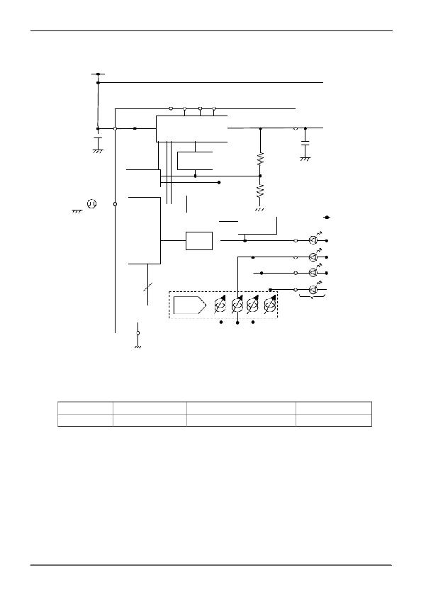
● Application Circuit Example
White LED Application(VOUT not used)
Battery
Datasheet
VBAT
×1, ×1.5, ×2
VOUT
Cin
=1 μ F
Pulse
EN
Charge Pump
Mode Control
Charge pump
Over Voltage
Protect
OSC
Cout
=1 μ F
Generator
Enable/
Brightness
Control
TSD
Vout Control
LED1
VDD
LED2
LED3
6
Current
LED4
Vf
DAC
GND
Figure 17. Block Diagram and Circuit Example
● Selection of Components Externally Connected
Capacitor (Use a ceramics capacitor with good frequency and temperature characteristics.)
Symbol
Cout,Cin,C1,C2
Recommended value
1 μ F
Recommended parts
GRM188B11A105KA61B(MURATA)
Type
Ceramics capacitor
Connect an input bypass capacitor Cin between VBAT and GND pin and an output capacitor Cout between VOUT and GND
pin in proximity. Place both C1P-C1N and C2P-C2N capacitors in proximity to the chip. Furthermore, select a ceramics
capacitor with a sufficient rating for voltage to be applied.
When the parts not listed above are used, the equivalent parts must be used.
www.rohm.com
? 2012 ROHM Co., Ltd. All rights reserved.
TSZ22111 ? 15 ? 001
10/14
TSZ02201-0G3G0C200030-1-2
05.Nov.2012 Rev.001
发布紧急采购,3分钟左右您将得到回复。
相关PDF资料
BD1603NUV-E2
IC LED DRVR WHITE BCKLGT 10-VSON
BD1604MUV-E2
IC LED DRVR WHITE BCKLGT 16-VQFN
BD1754HFN-TR
IC LED DRIVR WHITE BCKLGT 8-HSON
BD2802GU-E2
IC LED DRIVER RGB 24-VCSP
BD6062GU-E2
IC LED DRIVER FALSH VCSP85H2
BD6066EKN-E2
IC LED DRVR WHITE BCKLT 28-HVQFN
BD6069GUT-E2
IC LED DRIVR WHITE BCKLGT 8-VCSP
BD6081GVW-E2
IC LED DRIVER BACKLIGHT 63SBGA
相关代理商/技术参数
BD1603NUV
制造商:ROHM 制造商全称:Rohm 功能描述:Backlight LED Driver for Small LCD Panels (Charge Pump Type)
BD1603NUV_1
制造商:ROHM 制造商全称:Rohm 功能描述:Charge Pump type LED driver for mobile instrument
BD1603NUV_11
制造商:ROHM 制造商全称:Rohm 功能描述:Backlight LED Driver for Small LCD Panels (Charge Pump Type)
BD1603NUV-E2
功能描述:LED照明驱动器 Backlight LED Driver for Small Panel RoHS:否 制造商:STMicroelectronics 输入电压:11.5 V to 23 V 工作频率: 最大电源电流:1.7 mA 输出电流: 最大工作温度: 安装风格:SMD/SMT 封装 / 箱体:SO-16N
BD1604MUV
制造商:ROHM 制造商全称:Rohm 功能描述:4-Parallel white-LED Driver for mobile phone
BD1604MUV_1
制造商:ROHM 制造商全称:Rohm 功能描述:4-Parallel white-LED Driver for mobile phone
BD1604MUV_11
制造商:ROHM 制造商全称:Rohm 功能描述:Backlight LED Drivers for Small LCD Panels (Charge Pump Type)
BD1604MUV-E2
功能描述:LED照明驱动器 Backlight LED Driver for Small Panel RoHS:否 制造商:STMicroelectronics 输入电压:11.5 V to 23 V 工作频率: 最大电源电流:1.7 mA 输出电流: 最大工作温度: 安装风格:SMD/SMT 封装 / 箱体:SO-16N
